4.7. Well Integrity
4.7.1. Description
This application provides the following features as the monitoring tools for well integrity in geothermal reservoir.
4.7.2. Inputs
Caliper Log: Only LAS version up to 2.0 is supported. Log file should have DATE or PID mnemonic to track logging date. In addition, finger channels should be named as D01, where the measurement represents the double radii measurement.
Well Schematic: The well schematic is created in Well Schematics application.
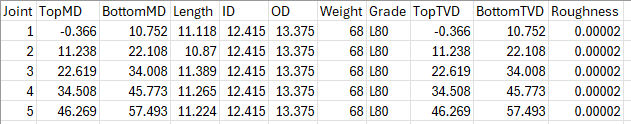
Well Tally: Tally file should follow given format:
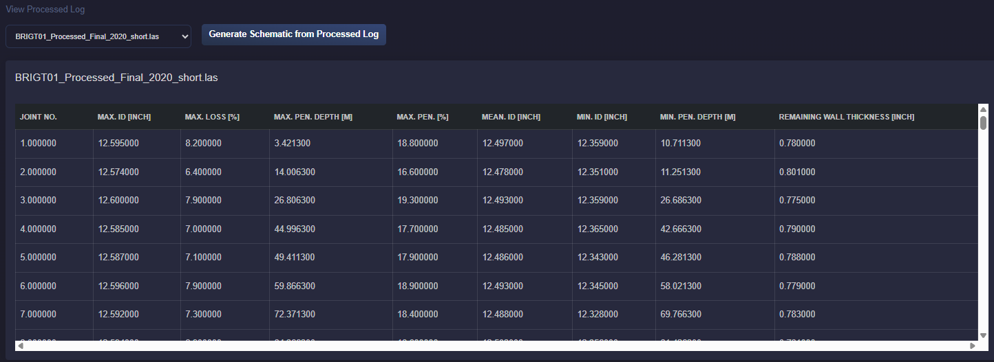
4.7.3. Caliper Log Processing
Log processing begins as soon as the log is uploaded. Processing involves calcualtaing following parameters per each well joint:
Maximumum, Minimum and Average ID
Maximumum loss pecentage
Maximumum penetration and corresponing depth
Minimum penetration and corresponing dept
Remaining wall thickness for the most pesimistic case
Note: Logs should be calibrated to depth reference which is alligned with the well schematic.
4.7.4. Corrosion Monitoring
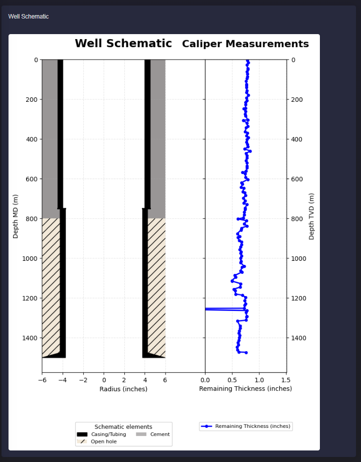
Remaining wall thickness can be viewed in the well schematic as per selected processed log.
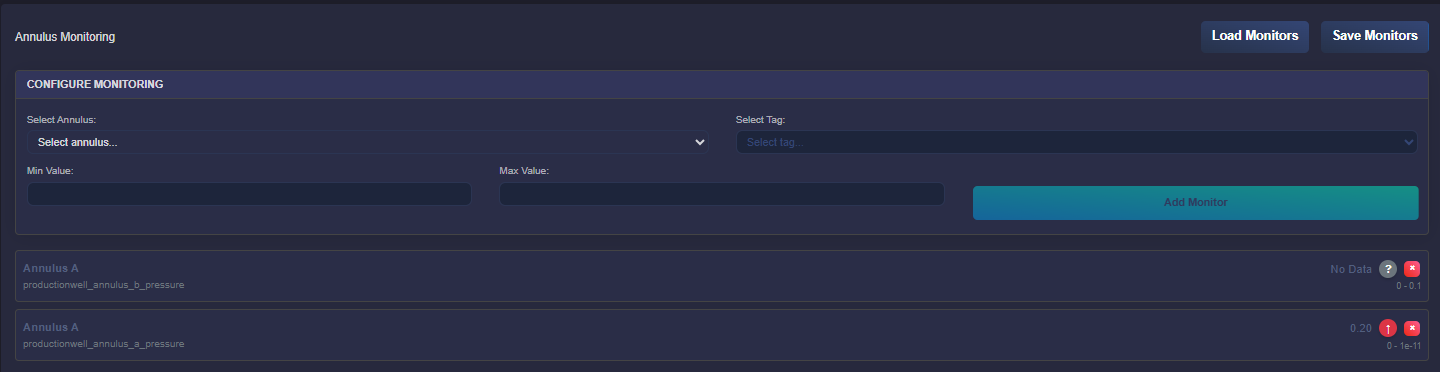
4.7.5. Annulus Monitoring
Annulus pressure can be monitored for a given well annulus based on the well schematic and notification can be set by providing min and max values.